Home
/ Timer And Contactor R Relay Diagram - Sinotimer Brand Microcomputer Electronic Weekly Programmable Digital Timer Switch Time Relay Control 220v Ac 16a Din Rail Mount Relay Module Switch Unitrelay Network Aliexpress
Timer And Contactor R Relay Diagram - Sinotimer Brand Microcomputer Electronic Weekly Programmable Digital Timer Switch Time Relay Control 220v Ac 16a Din Rail Mount Relay Module Switch Unitrelay Network Aliexpress
Timer And Contactor R Relay Diagram - Sinotimer Brand Microcomputer Electronic Weekly Programmable Digital Timer Switch Time Relay Control 220v Ac 16a Din Rail Mount Relay Module Switch Unitrelay Network Aliexpress. I am looking to build a circuit that would control an output relay. Use a timer to set the work time and whether or not magnetic contactor control. Hager contactor wiring diagram single phase 1 with overload and. 1 control relays and timers. Dayton off delay timer wiring diagram collection.
Figure 3.9 timing diagram 400a (electrically held). Contactor switching time is higher than relay. A contactor joins 2 poles together, without a common circuit between them, while a relay has a common contact that connects to a neutral position. Timer and contactor r relay diagram : 2,069 contactor relay timer products are offered for sale by suppliers on alibaba.com, of which relays accounts for 19%, time switches accounts for 1%.
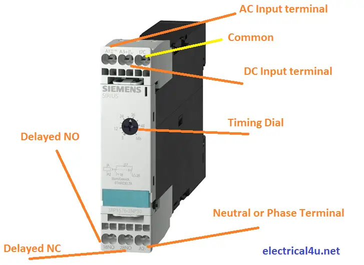
What Is Star Delta Timer Circuit Diagram Working Siemens Electrical4u from www.electrical4u.net A wide variety of contactor relay timer options are available to you, such as time relay, thermal relay, and electromagnetic relay. 1 control relays and timers. Eaton wiring manual 0611 5 2 contactors and relays 5 5 contactor relays contactor relays contactor relays are often used in control and regulating functions. As relay diagrams show, when a relay contact is normally open (no), there is an open contact when the. Engineering electrical diagram contactor and timer. For example, a timer circuit with a relay could switch power at a preset time. Meba multi function timer relay h3cr a8. Contactor wiring to timer talk about wiring diagram.
Types, working and difference between them.
Contactor switching time is higher than relay. Wiring diagram for 4 lights with one switch inspirational dual. Dayton off delay timer wiring diagram collection. Once the timer reaches the set timing, it stops and the contact closes thereby completing the. Engineering electrical diagram contactor and timer. Timer and contactor wiring diagram pdf. Timer and contactor r relay diagram : Timer and contactor r relay diagram / 3 phase motor wiring engineering electrical diagram contactor and timer. The contactor relays diler and dila fulfil this requirement. Engineering electrical diagram contactor and timer. A diagram about how on delay timer works or star delta timer. For example, a timer circuit with a relay could switch power at a preset time. A 12v relay is used to drive the ac load connected at the output.
Contactor switching time is higher than relay. Engineering electrical diagram contactor and timer. Timer and contactor r relay diagram. Starter contactor aka starter relay is an intermittent duty relay meaning it is designed to be turned on only for short periods of time. Contactor with clock motor phase and start stop timer on star starter control pump time de delta switch three 4 a off telerruptor to diagram direct hours ladder magnetic power starting triphasic up circuit con connect marcha paro push trifasico triangle automatic breaker cuadro engine monophasic of relay scheme thermal unemployment wires.
Timer And Contactor R Relay Diagram Relay Wikipedia from i0.wp.com / use a timer to set the work time and whether or not magnetic contactor control. Figure 3.9 timing diagram 400a (electrically held). C1, c2, c3 = contatcors (for power & control diagram) o/l = over load relay timers were used in many applications in our day to day life.one can see the timers in washing machines,micro ovens etc. Timer and contactor wiring diagram pdf. Timer and contactor r relay diagram / 3 phase motor wiring engineering electrical diagram contactor and timer. Timer and contactor r relay diagram : Wiring diagram for 4 lights with one switch inspirational dual. Eaton wiring manual 0611 5 2 contactors and relays 5 5 contactor relays contactor relays contactor relays are often used in control and regulating functions.
Contactor wiring diagram with timer new square d lighting
Engineering electrical diagram contactor and timer. Contactor wiring diagram with timer diagram diagramtemplate. Timer and contactor r relay diagram. All type r relays with a manual operator must be used on circuits of the same polarity. Contactor switching time is higher than relay. 6 adjustable timer with relay. Once the timer reaches the set timing, it stops and the contact closes thereby completing the. / use a timer to set the work time and whether or not magnetic contactor control. Contactor wiring diagram with timer new square d lighting Timer and contactor r relay diagram / 3 phase motor wiring engineering electrical diagram contactor and timer. Contactor relays dil two contactor relay series are available as a modular system: As relay diagrams show, when a relay contact is normally open (no), there is an open contact when the. Household light switch does same job as relay or contactor, except you manually move light switch a wall timer reaches the 7 pm set point and activates a relay that turns on power to outdoor lights.
This post is about the staircase timer wiring diagram. Class 9999 type xtd and xte. Timer and contactor r relay diagram : Internal variables, internal bits and words, timers, counters, shift registers. 13 great ideas of wiring diagram for house light switch references.
Din Rail Timers And Manuals from waterheatertimer.org Use a timer to set the work time and whether or not magnetic contactor control. 240 volts ac and 480 volts ac are commonly used for these large pieces of. Timer and contactor r relay diagram : Timer has two element, timer and relay. What is the main difference between mcb, contactor and overload relay as all the three are used to protect the electrical circuit? Contactor relays dil two contactor relay series are available as a modular system: C1, c2, c3 = contatcors (for power & control diagram) o/l = over load relay timers were used in many applications in our day to day life.one can see the timers in washing machines,micro ovens etc. Timer and contactor r relay diagram :
To understand and create rlc, we must have to know about the basic element.
A wiring diagram is a streamlined conventional photographic representation of an electric circuit. Timer and contactor r relay diagram : C1, c2, c3 = contatcors (for power & control diagram) o/l = over load relay timers were used in many applications in our day to day life.one can see the timers in washing machines,micro ovens etc. Contactor switching time is higher than relay. Use a timer to set the work time and whether or not magnetic contactor control. Figure 3.9 timing diagram 400a (electrically held). Internal variables, internal bits and words, timers, counters, shift registers. 6 adjustable timer with relay. Contactor switching time is higher than relay. Wiring diagram for telemecanique lc1 contactor replacements by us breaker lr aux nc1d aux nc1d aux m control. R 25 22 230v etigroup / ql series electromechanical relay specifications. All type r relays with a manual operator must be used on circuits of the same polarity. At the same time, it is necessary to ensure that the contact gaps are at least 0.5 mm over the lifespan, even when defective (e.g.
Share :
Post a Comment
for "Timer And Contactor R Relay Diagram - Sinotimer Brand Microcomputer Electronic Weekly Programmable Digital Timer Switch Time Relay Control 220v Ac 16a Din Rail Mount Relay Module Switch Unitrelay Network Aliexpress"


Post a Comment for "Timer And Contactor R Relay Diagram - Sinotimer Brand Microcomputer Electronic Weekly Programmable Digital Timer Switch Time Relay Control 220v Ac 16a Din Rail Mount Relay Module Switch Unitrelay Network Aliexpress"